General Forth Words for GPIO On The STM32F103
This blog entry goes into the design of a Mecrisp Forth wordset that allows you to program the GPIO ports. This is typically one of the first things one learns to do on a microcontroller, and is usually taught by getting one or more LEDs to flash. We will hook up LEDs to the PC10 and PC8 pins of the STM32P103 board and write some code to get them to flash.
If one were to write a code to do this in an algol-derived programming language like C or the C-like language used in the Arduino programming environment, one would usually write code that involves calls to built-in libraries. For an Arduino, the code might look something like:
#define LED PC10
void setup() {
  // initialize digital pin LED_BUILTIN as an output.
  pinMode(LED, OUTPUT);
}

// the loop function runs over and over again forever
void loop() {
  digitalWrite(LED, HIGH);   // turn the LED on (HIGH is the voltage level)
  delay(200);                       // wait for 200 ms
  digitalWrite(LED, LOW);    // turn the LED off by making the voltage LOW
  delay(200);                       // wait for 200 ms
}
This code sets up port C pin 10 in the function setup as an output using a function called pinMode, and uses a separate function loop which, in turn, calls a function called digitalWrite to set the pin to high or low with a delay set by a call to the function delay, in this case of 200 ms. One may also need a function to turn on the clock to port C if it can’t already be assumed to be on.
Presumably one would include calls to these functions within a loop in a function main to complete the program. This is not too difficult to follow, if you ignore all the infrastructure like semicolons and explicit type declarations. And it’s nice to be able to call these pre-built functions, provided you can remember the function name someone else decided upon, and that you don’t want to do things that are not catered for in the function. For example, the pinMode function does not have an input parameter that allows you to set the clock speed of the GPIO pins, which is an option that is available on the chip. Of course you could write your own pinMode function, but perhaps other functions in the library would use the original pinMode function with a different clock speed. Because you didn’t write the code, you don’t easily know what was done in the library.
Forth encourages programmers to look at a problem like this differently. Rather than forcing the programmer’s application to always look like the syntax of the programming language, Forth makes it very easy for a programmer to make words that define a domain-specific language that is tailored to solving that particular problem. By combining the concept of the dictionary and the implicit passing of parameters on the stack, this domain-specific language can be made to look like a set of commands to the microcontroller that are set up to control any GPIO port. And with a little thought, they can be made quite general.
Pre-reading
Before we can make the generalised GPIO words, we need to make some words that allow us to save bit patterns to registers without changing the remaining bits in those registers. These nondestructive bit setting and resetting words were introduced previously here in a previous blog entry. It’s best to go through that and make sure you understand those words before going any further.
How to control GPIO
To get a GPIO port working you need to do three things:
- Turn on the clock
- This is done using the
RCC_APB2ENRclock enabling register
- This is done using the
- Set the pin on the port to be an input or an output
- This is done using the
GPIOx_CRL(for pins 0-7 on a given port) orGPIOx_CRH(for pins 8 through 15).
- This is done using the
- Write or read the value of the bit(s) we are interested in, i.e.
- Set or reset the bit in the
GPIOx_ODRregister to turn an output on or off, or - Read the value of the pin in the
GPIOx_IDRregister if you want to know if an input is on or off.
- Set or reset the bit in the
GPIO Registers and Where to Find Them
One of the neat things about the design of the registers in the STM32F103 chip is that each of the GPIO ports is separated by a consistent offset ($400) and each of the control registers for any port is at the same offset from the base address of that port. This consistency means that we are able to write generalised words that can be used to set any aspect of the behaviour of any of the GPIO pins on any of the ports.
The GPIO ports in the STM32F103 have addresses that can be found in the STM32F103 reference manual, in Section 3.3. All of ports A through E are in consecutive peripheral base addresses, as shown in the table below:
| Port | Base Address |
|---|---|
| A | $4001 0800 |
| B | $4001 0C00 |
| C | $4001 1000 |
| D | $4001 1400 |
| E | $4001 1800 |
Each of these ports will have several registers, separated by 4 bytes from each other, that control the behaviour of these registers. In our GPIO library we will concentrate only on the most used of these registers, though once you know how to make the words, it will be easy to add words to change the other registers if necessary.
For the GPIO control we are interested in, we will be setting values in the registers GPIOx_CRL, GPIOx_CRH, GPIOx_IDR and GPIOx_ODR. Although there are other registers such as the GPIOx_BSRR set/reset register and the GPIOx_LOCKR lock register, I don’t use them, so won’t be using them in this wordset. I have also avoided the AFIO alternate function registers here, because we will come to them when using the timers later on.
In addition to the GPIO registers we also add the port clock setting register, RCC_APB2ENR that controls the clock of the five ports. By default, my Mecrisp has ports A, B and C switched on, so I don’t tend to set it. But for the sake of the exercise we will provide words that use that clock control register as well to turn on the ports.
Domain-specific Language Design
Before writing a Forth code, I like to imagine how I would call the words to operate the GPIO. This gives me a starting point for the implementation of the wordset itself, because I then know what the final words should look like. I would like to be able to use the same words to control any of the ports, which means that I would need to have a word that indicates the base address of the port, with words like GPIOA, GPIOB etc returning the base addresses of those ports. This allows me to write words that permit commands like GPIOA enable to enable the clock for GPIO port A.
Control commands based upon words like this would look something like
GPIOC enable  	\ enable port C
GPIOC 10 ppout 	\ set port to push-pull output (50 MHz)
GPIOC 10 GPon	\ turn on GPIOC pin 10
GPIOC 10 GPoff	\ turn off GPIOC pin 10
Words like this can then be included in more complex words such as lflashes to flash a particular pin a certain number of times
GPIOC 10 20 lflashes \ flash GPIOC pin 10 20 times
and extended to do still more complex things like running light displays, all building upon these primitive port control words. At this point it’s worth comparing the Forth control method with the Arduino code at the start of this blog entry. Once the words have been made, the Forth code produces a direct command language available to the Forth user that looks a little like Forth, but a lot like a language designed to control GPIOs (albeit with an infix way of inputting data). In contrast, the Arduino code always carries the baggage of looking like the programming language it was implemented in. This is, I think, one of the strongest arguments for the use of Forth as a programming environment for microcontrollers. For some, the fact that the Arduino code always looks consistent with other Arduino code is an advantage because only one syntax needs to be learned. I have always thought the Forth way of doing things is cleaner-looking when done properly.
Building the Wordset
Now that we know the way we want to control the GPIO, we need to make words that allow us to develop those words. In other words, we are designing the application from the top down and implementing from the bottom up, once we know what the top-level words look like.
Initialising the Port(s)
The initialisation word switches on the clock for the port. This is done by setting bits in the RCC_APB2ENR register, shown in Fig. 1.

Figure 1: RCC_APB2ENR Register
This register contains the clock enable bits for a number of peripherals, including all the GPIO ports. Notice that GPIOA through GPIOG are all consecutive (although the STM32F103RBT6 in the Olimex STM32P103 board that I am using only has ports A through E).
So to turn on the clock for a given port, we need to set bit 2 for port A, bit 3 for Port B etc. Assuming we are using the port address as the alias for PortA etc, we need a way to convert the address to the offset. We use the fact that the port addresses are $400 apart to subtract the address from port A’s address, divide by $400 and add 2 to determine the bit position we need to switch on.
First, we make constants for the base addresses of each port and for the RCC_APB2ENR register:
\ Address locations
$40010800 CONSTANT GPIOA
$40010C00 CONSTANT GPIOB
$40011000 CONSTANT GPIOC
$40011400 CONSTANT GPIOD
$40021018 CONSTANT RCC_APB2ENR
Now we make the enable and disable words that allow us to set or reset the clock for a given port using the set_bits word we declared in the previous blog entry on non-destructive bit setting:
\ Application words
: enable ( aPort -- )
  GPIOA - $400 / 2 +
  RCC_APB2ENR SWAP
  1 1 ROT
  set_bits ;         \ Turn on the clock
: disable ( aPort -- )
  GPIOA - $400 / 2 + \ Set location to shift to
  RCC_APB2ENR SWAP
  0 1  ROT
  set_bits ;         \ Turn on the clock
This allows us to use commands like GPIOA enable or GPIOC disable to enable or disable any of the ports. One should be careful about disabling whole ports, as sometimes these ports can be used for other peripherals. For example, USART1 is driven by pins on GPIO port A and switching that off may stop Forth from communicating with the terminal program!
Once we can enable the port, we next have to be able to determine whether a pin is an input or an output. To do this, we need to declare the positions of the control registers for this particular port. Because the designers of the STM32F103 were nice enough to make the control register offsets the same for all the ports, we can define the registers as offsets from the base address.
\ Register offset definitions
\ NB aPort is the address of the port (eg GPIOA, as defined above)
: CRL ( aPort -- aPort + CRL ) ;
: CRH ( aPort -- aPort + CRH ) $04 + ;
: IDR ( aPort -- aPort + IDR ) $08 + ;
: ODR ( aPort -- aPort + ODR ) $0C + ;
Thus, the commands GPIOA ODR will provide the address of the output data register for GPIOA, and GPIOE ODR provides the equivalent address for GPIOE. This means that you don’t need to declare constants for each of the registers of each of the ports separately.
To set a particular pin of a particular port to be an input or an output. To do this, we must set 4 bits: 2 CNF bits and 2 MODE bits. These 4 bits are indexed by 4 bits per pin, stretched over 2 registers – GPIOx_CRL for pins 0–7 and GPIOx_CRH for pins 8–15. The two lower MODE bits determine whether the pin is an input or an output while the CNF bits outline what kind of input or output the pin is. The arrangement is shown in Fig. 2 for the CRH register.

Figure 2: GPIOx_CRH register
| MODE | GPIO type |
|---|---|
| 00 | Input |
| 01 | 10 MHz output |
| 10 | 2 MHz output |
| 11 | 50 MHz output |
| CNF | GPIO type |
| If input | |
| 00 | Analog |
| 01 | Floating |
| 10 | Pull up/pull-down |
| 11 | Reserved |
| If output | |
| 00 | General purpose push/pull |
| 01 | General purpose open drain |
| 10 | Alternate function push/pull |
| 11 | Alternate function open drain |
Any given pin of any given port can be set with any combination of these 4 bits, depending on how the GPIO is to operate. To make this work in a general way, I have made a word called GPset that takes the port address, pin number and the 4-bit string from the table above and uses our non-destructive set-bits word to set the appropriate 4 bits in the CRL or CRH register. We can then make words describing the type of input or output that you would like that pin to be, using the bit pattern with the call to GPset. The GPset word must choose whether the CRL or CRH register must be written to, based upon the pin number on the stack. This is done with an IF ... ELSE ... THEN statement.
: GPset ( aPort pin# porttype -- )
  \ Set a pin to output
  \ porttype is a 4-bit pattern
  >R
  DUP 7 >
  IF 7 - SWAP CRH SWAP ELSE 1+ SWAP CRL SWAP THEN
  4 * 1-
  R> 4 ROT  set_bits  ;
: ppout     ( aPort pin# -- ) %0011 GPset ; 	\ Set port pin to push-pull output, 50 MHz
: ppout2MHz ( aPort pin# -- ) %0010 GPset ; 	\ Set port pin to push-pull output, 2 MHz
: afout     ( aPort pin# -- ) %1011 GPset ; 	\ Set port pin to AF output, 50 MHz
: ppin      ( aPort pin# -- ) %1000 GPset ; 	\ Set port pin to push-pull input
: ain       ( aPort oun# -- ) %0000 GPset ; 	\ Set port pin to analog input
We can then issue commands like GPIOC 10 ppout to set pin 10 of GPIO port C to a 50 MHz push-pull output, or GPIOB 8 ppin to set pin 8 of GPIO port B to an input.
Once we can switch the ports on or off and declare the type of input or an output for a given pin of a given port, all that remains is to read from (for an input pin) or write to (for an output pin) the port. The reading or writing are done with the lower 16 bits of the IDR (for inputs) or ODR (for outputs) register. Again, we use set_bits for the setting, but for the reading we use LSHIFT for reading the port, using bitwise AND to set all the other bits to zero, leaving either a true (for a 1) or false (for a 0) at the bit position of interest.
: GPon ( aPort pin# -- )
  \ Turn on a pin for an output port
  SWAP ODR SWAP %1 1 ROT set_bits ;
: GPoff ( aPort pin# -- )
  \ Turn off a pin for an output port
  SWAP ODR SWAP %0 1 ROT set_bits ;
: GPon? ( aPort pin# -- fl )
  \ Check to see if an input is switched on
  SWAP IDR @ 1 SWAP LSHIFT AND = ;
And that’s pretty much all that’s needed to get a general-purpose GPIO wordset working that allows bits to be manipulated as needed. The remainder of the file provides a demonstration of the operation of this wordset in making simple LED flashing words. Set up a red LED and a 220 Ohm resistor going from pin 8 and pin 10 to ground. The setup for pin 10 is shown in Fig. 3.
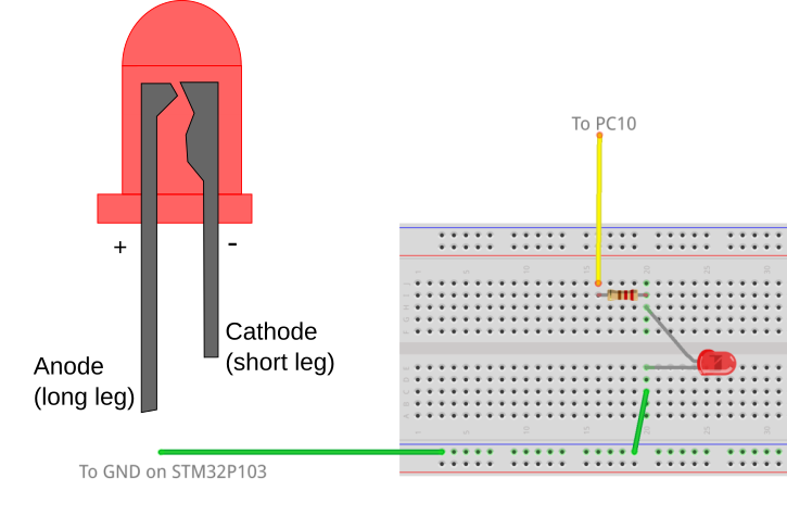
Figure 3: Setup for LED on Pin 10 of GPIOC
The setup here is done with the port driving pin 8 and pin 10 directly from the port. The port outputs can sink enough current to drive a LED, though it’s probably better to connect the anode to the +3.3V supply on the board and the ground-connection to the port. If you connect the ports this way, you can drive more current as the port is sinking to ground.
The rest of the code provides words that can flash an LED a given number of times using the lflashes word, or can flash the two outputs using the alternate word. Note that lflash is built upon GPon and GPoff, lflashes and alternate are built upon lflash. The ms word used here employs a software loop to generate the delay for the pin flash. It’s set up for a 72 MHz clock speed, and the delay multiple scale may need to be changed for a lower value if the clock speed is lower. In a future post we’ll work out how to make a more accurate timing word using the STM32F103’s built-in timers, but this is sufficient for illustration. The comments at the end of the code show you how this domain-specific GPIO language can be used to control input and output ports.
I hope this short example shows you how Forth can take some very simple primitive words and develop a language specifically tailored to a particular interactive programming task. The full source is reproduced below.
\ GPIO General Access Wordset
\ This is an example of how you can use Forth to make a language for
\ operating your GPIO ports on the STM32F103 processor
\ Note that this particular code only deals with setting an entire
\ high or low part of a port to an input or an output
\ Also note that the ms word is highly dependent on the clock speed
\ Note that these words can be used with any of ports A, B, C and D
\ and can configure any output.
\
\ Sean O'Byrne 03/2022
\ Code released under terms of the Gnu Public Licence Version 3

\ Address locations
$40010800 CONSTANT GPIOA
$40010C00 CONSTANT GPIOB
$40011000 CONSTANT GPIOC
$40011400 CONSTANT GPIOD
$40021018 CONSTANT RCC_APB2ENR

\ Register offset definitions
\ NB aPort is the address of the port (eg GPIOA, as defined above)
: CRL ( aPort -- aPort + CRL ) ;
: CRH ( aPort -- aPort + CRH ) $04 + ;
: IDR ( aPort -- aPort + IDR ) $08 + ;
: ODR ( aPort -- aPort + ODR ) $0C + ;

\ Utility words

: ones ( n -- %11..1 )
  \ Generate a binary number consisting of n 1s
  1 SWAP 1- 0 ?DO 2 * 1 + LOOP ;

: pos_shift ( nbits pos -- nbits shift# )
  \ Determines the number of bits to shift given the position of the MSB
  \ and the number of bits
  OVER - 1+ ;

: not_mask ( nbits shift -- shift mask )
  \ Generate mask consisting of 1s everywhere but where we want to
  \ change bits
  SWAP ones OVER LSHIFT NOT ;

: set_bits ( addr %n nbits pos -- )
  \ Stores a bit pattern bits starting at a given bit position at address adr
  \ bits consists of nbits 1s and 0s at position pos in a 32-bit word.
  \ Non-intrusive for all other bits.
  \ Usage:
  \        GPIOC CRH %0011 4 7 set_bits
  \ This would place the 4-bit pattern %0011 at bit position 7 in GPIOC_CRH.
  \ The word b counts the bits (including leading zeros) in the binary number.
  \ Note that b can only be used interactively, not within a word definition.

  pos_shift \ Determine number of bits to shift pattern
  not_mask  \ Set bit pattern to AND with
  >R
  LSHIFT    \ Set bit pattern to OR with
  OVER @
  R>
  AND       \ AND with mask to get 0s at correct bit positions
  OR        \ OR with bit pattern to nonintrusively set
  SWAP ! ;  \ Store new bit pattern at address

\ Application words
: enable ( aPort -- )
  GPIOA - $400 / 2 +
  RCC_APB2ENR SWAP
  1 1 ROT
  set_bits ;         \ Turn on the clock

: disable ( aPort -- )
  GPIOA - $400 / 2 + \ Set location to shift to
  RCC_APB2ENR SWAP
  0 1  ROT
  set_bits ;         \ Turn on the clock

: GPset ( aPort pin# porttype -- )
  \ Set a pin to output
  \ porttype is a 4-bit pattern
  >R
  DUP 7 >
  IF 7 - SWAP CRH SWAP ELSE 1+ SWAP CRL SWAP THEN
  4 * 1-
  R> 4 ROT  set_bits  ;

: ppout     ( aPort pin# -- ) %0011 GPset ; 	\ Set port pin to push-pull output, 50 MHz
: ppout2MHz ( aPort pin# -- ) %0010 GPset ; 	\ Set port pin to push-pull output, 2 MHz
: afout     ( aPort pin# -- ) %1011 GPset ; 	\ Set port pin to AF output, 50 MHz
: ppin      ( aPort pin# -- ) %1000 GPset ; 	\ Set port pin to push-pull input
: ain       ( aPort pin# -- ) %0000 GPset ; 	\ Set port pin to analog input

: all_outputs ( aPort -- ) DUP CRH $33333333 SWAP ! CRL $33333333 SWAP ! ;
: all_inputs  ( aPort -- ) DUP CRH $88888888 SWAP ! CRL $88888888 SWAP ! ;

: GPon ( aPort pin# -- )
  \ Turn on a pin for an output port
  SWAP ODR SWAP %1 1 ROT set_bits ;

: GPoff ( aPort pin# -- )
  \ Turn off a pin for an output port
  SWAP ODR SWAP %0 1 ROT set_bits ;

: GPon? ( aPort pin# -- fl )
  \ Check to see if an input is switched on
  SWAP IDR @ 1 SWAP LSHIFT AND = ;

\ LED Flashing Routines
\ Here are some example words to make LEDs flash

\ Setup for LED flashing
GPIOC enable
GPIOC 10 ppout
GPIOC 8 ppout
0 GPIOC ODR H!

200 VARIABLE time \ flash delay time, in ms
12000 VARIABLE scale

\ Software ms loop
: ms scale @ * 0 do loop ; \ change number to get accurate ms timing

: pulse ( n -- ) GPIOC 10 2dup GPon rot ms GPoff ;

: lflash ( aPort bit_pattern -- ) \ Flashes PC10 for the appropriate number of ms
  2DUP GPon time @ ms GPoff time @ ms ;

: lflashes ( aPort pin# n -- ) \ Flashes PC10 n times
  0 ?DO 2DUP lflash LOOP 2DROP ;

: alternate ( n -- )
  0 ?DO GPIOC 10 lflash time @ ms GPIOC 8 lflash time @ ms LOOP ;


\ Now you can try the following after hooking up an LED and resistor to
\ port C pin 10 and another to port C pin 8...
\ Example usage below
\ GPIOC port_enable
\ GPIOC all_outputs
\ GPIOC 10 GPon
\ GPIOC 10 GPoff
\ GPIOC 10 lflash
\ GPIOC 8 lflash
\ GPIOC 10 20 lflashes
Comments
I would like to thank you for enlightening and well-written post on using Mecrisp Forth to program the generic stm32f103 boards. i have dabbled a little in Forth on pc’s, but struggling a little when trying to apply that experience to microcontroller level hardware specifics, I found your article very useful.
As a side note I spotted what appears to be a small typo: The definition of the word “afout” should evidently not contain the bit-pattern %1000 (same as for “ppin”), but e.g. %1001″.
Thanks Martin, sorry I missed your comment before, but the signal-to-spam ratio on my site is not great. And thanks for the correction. I’ll correct the page to reflect the correct bit pattern.
I’m glad you liked the post: comments like this are motivating to me. I’m hoping to turn some of these ideas into a book on using Forth on microcontrollers one day. I think one of the hardest parts about learning Forth when familiar with other languages is the idea of building a domain-specific vocabulary to implement a solution. This is quite different to the way in which other languages tackle problems like this, and I wanted to emphasise this on the blog entry. There are many ways in which this could be implemented (this is the beauty and frustration of Forth), and some of them may be more elegant than this, but I think this gets the idea across.
In “The full source is reproduced below.” section, you are missing the “$40021018 CONSTANT RCC_APB2ENR” definition to allow proper operation if you have not done the preceding exercise of defining words one by one. Thanks for this site allowing me to better understand Mecrisp-Stellaris.
Thanks for pointing that out, Christian.