HyperScience

Solving Equations for Physical Understanding

Introduction

I have been teaching undergraduate aerospace and mechanical engineering students and physics students for more than 20 years. In that time I have made and heard others make complaints that our students are not comfortable with mathematics and that this problem is getting worse with time, particularly in dealing with the differential equations (D.E.s) that show up all the time in engineering problems. I suspect that teachers have always made such statements to a greater or lesser extent, at least partially because we forget how many mistakes we made when we first started learning to be engineers. Or perhaps some of it is because the people who teach engineering are drawn from the top cohort of engineering students, and only learn about the continuum of talent in undergraduate courses when they are asked to teach them. But there also seems to be some evidence to suggest that students are having more difficulties now than previously with mathematics, particularly for the more advanced topics like the use of D.E.s.

I can blame the internet, of course — students have difficulty with finding time for the pen-and-paper practice that is required to achieve facility with and understanding of the mechanics of basic mathematical techniques like differentiation and integration because students have many more (and many more fun) things they (could/should/must/would like to) do on a computer.

But if I am honest with myself, and look back through the mists of time, I was not so hot at this process myself when I was an undergraduate student, and I didn’t have the distractions that our current generation of students have.

So what causes this problem and how do we solve it? My working hypothesis is that at least some of the problems arise from not linking the mechanics of the mathematics with our physical experience. Students learn mathematics as an abstract set of tools for solving equations, and then we expect them to use those tools to solve physical equations without linking the equation(s) to the students’ intuitive understanding of the physics of the problem systematically: many students treat the problem and its mathematical solution as two completely separate and unrelated problems.

In the particular case of aerospace engineering, this experience is encapsulated by a student being repeatedly exposed to the Navier-Stokes equations, a set of formidable partial differential equations that can describe most fluid-dynamical problems but can only be solved analytically in a few simple cases. We explain those cases and students dutifully copy down the methods and repeat them to us in exams at the end of the term, if we and they are lucky.

Now the Navier-Stokes equations are wonderful, but they are difficult to understand for most engineering students because they are so general and so very nonlinear. The pedagogical principle that we follow in aerospace engineering seems to be that if you show these equations to students frequently enough they will eventually `stick’ through repetition and familiarity. So we keep exposing the students to these equations and how they can be manipulated into more immediately useful simplified forms until something magical happens and the student starts to understand how to use them. For the best students, this is the case, but many more students get by on memorising specifics sufficiently well to get through the exams, never really coming to terms with what the equations mean physically and how they can be simplified.

The approach to engineering mathematics education I’ve just mentioned is equivalent to a magician telling a new apprentice to read a book on how to saw their assistant in half, follow the instruction and perform the trick. It’s a process more likely to result in a lot of bisected assistants and a very dispirited apprentice magician than it is to produce a successful magic trick.

Of course those who have a good understanding of the Navier-Stokes equations have the ability to solve a wide range of problems in fluid mechanics by going from the general problem to specific cases of interest, making the right sorts of simplifications at the right times. This is what we would like our students to be able to do. But this ambition is very difficult to achieve when you are learning, and so it seems to me that a better approach involves solving simpler problems and working your way up to the more difficult ones as you gain experience. If the simpler problems are chosen carefully, you can teach the basic ideas without the complications that make understanding the concepts unnecessarily difficult.

In terms of our magician analogy, it would seem more sensible to teach a simpler and less frustrating trick, like pulling a rabbit out of a hat (I don’t know if this is actually less simple than sawing an assistant in half, but let’s assume it is, because the process is reversible if you get it wrong, unlike sawing someone in half). One might start with a stuffed rabbit and a top hat and go through the process several times, eventually getting the student to try it independently and with a live rabbit. Then perhaps teach them how to do the same thing with a chef’s hat or a sombrero … until the student realises that they are all just hats and that the type of hat does not change the trick — the hats are all just hats.

For differential equations, the equivalent to learning magic this way is to solve different first-order D.E.s describing different problems. Not initially as a purely mathematical exercise, but by some kind of approximate method that makes use of the student’s physical intuition and their understanding of the problem. Once this method is determined, the more precise problem can be tackled mathematically with some knowledge of what the solution should look like and why.

The sort of thing that might work well is described in the excellent book “Solving equations with physical understanding” by J.R. Acton and P.T. Squire: ISBN 978-0852747995. Unfortunately the book now appears to be out of print. It details a method for the approximate solution of ordinary and partial differential equations that relies on the physical behaviour of the problem rather than on the mathematical techniques involved in the direct solution of the D.E. You could think of it as a `back of the envelope’ solution for differential equations that provides physical insight about the meaning of the solution to the D.E. By tackling simple differential equation problems with this method and then doing the same thing more formally, we can consciously combine our physical intuition about the behaviour of the differential equation with our mathematical understanding of its solution. This helps bridge the gap between a purely mathematical understanding of differential equations and the ability to use D.E.s to sqolve new engineering problems from scratch, which should ultimately be our aim in looking at these equations in the first place. By solving many of these simple problems in a range of domains, engineering students are able to develop their ability to recognise the fact that, like the magician’s apprentice, for many of these problems although the hats look different, they are all just hats.

To give an example, after this too-long introduction, I’ll reproduce the first example used in the book, involving a familiar physical problem that involves solving a first-order differential equation. We will take the equation, make a qualitative sketch (QS) of the functional form that the solution should take, using our physical understanding of the problem. Then we will substitute that test function (TF) into the equation to determine a model for the physical behaviour. Then, because the problem is simple enough, we will compare the approximate solution obtained through this process (called in the book the QSTF process) with the actual solution obtained by solving the differential equation.

Exponential Growth and Decay

Many problems involve an exponential-shaped growth or decay from an initial value that is fixed to gradually rise or fall until it very closely approaches a final value, which mathematicians refer to as an asymptotic approach to that value that, like Achilles in Zeno’s paradox of his race with the tortoise, never quite gets to that final value. As an example of an exponential decay, Fig. 1 shows three plotted decay curves starting from a value of \(u_0\) at \(t = 0\) changing asymptotically to zero with three different time constants.ExpDecay.jpg
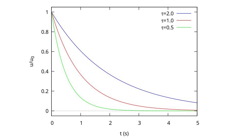
Figure 1: Exponential decay curves for 3 time constants

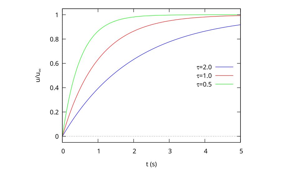
Other problems will involve an exponential rise from zero to an asymptotic limit, and can be described by the equation

\begin{equation}
\label{orgac57ec5}
u = u_\infty(1 – e^{-t/\tau})
\end{equation}

As a plot, this looks like Fig. 2
ExpRise.jpg

Figure 2: Exponential rise curves for 3 time constants

The most general case of a smooth exponential transition between two non-zero states \(u_0\) and \(u_\infty\) is described by

\begin{equation}
\label{org7a2ccea}
u = u_\infty + (u_0 – u_\infty) e^{-t/\tau}
\end{equation}

Why is the Exponential Form so Important?

As we shall soon see, there are other possible functional forms than Eq. \eqref{org7a2ccea} that we could have chosen that have a similar asymptotic growth or decay behaviour with time. But there is a significant advantage to the natural exponential form because the natural exponential’s derivative is the same as that of the original function, i.e.

\begin{equation}
\frac{d}{dx} e^x = e^x
\end{equation}

or is a constant factor times that function, like

\begin{equation}
\frac{d}{dt} e^{-t/\tau} = -\frac{1}{\tau} e^{-t/\tau}
\end{equation}

This means that the behaviour with time can be described using a single characteristic time parameter, \(\tau\). The physical meaning is that when t = \(\tau\), the solution will have changed by (1 – e^{-1}) = 63.2 per cent of the total change, and every subsequent \(\tau\) will be 63.2 per cent of the remaining change (i.e. 63.2 per cent of 36.8 per cent etc.).

Example: a Falling Rock

Consider the case of a rock falling under the influence of gravity and air drag. The differential equation that describes this behaviour is

\begin{equation}
\label{org885b28d}
m \frac{dv}{dt} = mg – bv^2
\end{equation}

\begin{equation}
[mass \times acceleration] = [gravity force – air drag]
\end{equation}

where \(b\) is the drag coefficient of the body, determined by its shape.

If dropped with an initial velocity of zero, the rock should increase its speed smoothly from zero until reaching a constant velocity when the forces balance, i.e. when

\begin{equation}
mg = bv^2
\end{equation}

or

\begin{equation}
v_\infty = \sqrt{\frac{mg}{b}}
\end{equation}

Although there are a number of ways in which the object could reach the final velocity, the simplest one associated with the gradual balancing of two forces might look like one of those in Fig. 2, with the time constant determined by the mass, the gravitational force and the drag coefficient of the object.

As an aside, notice how in the discussion above I snuck in the assumption that the drag was proportional to the square of the velocity of the object? In fact, this is only true at higher Reynolds numbers and the drag force would be linearly related to velocity at lower speeds. This is one of the dangerous aspects of treating the equation as being independent of the physical problem to be solved. Although the rock would need to be physically very small to have a low enough Re to be proportional to the velocity, I have still seen this form in several example problems in maths textbooks.

While the D.E. in Eq. 5 can be solved directly, we will find an approximate solution using our physical understanding of the problem. This involves 3 basic steps:

  1. making a qualitative sketch (QS) of the solution (we have done this already in Fig. 2)
  2. using this sketch to make a trial function (TF) that describes the equation;
  3. using the TF to determine a design formula for the time constant of the exponential rise

Qualitative Sketch

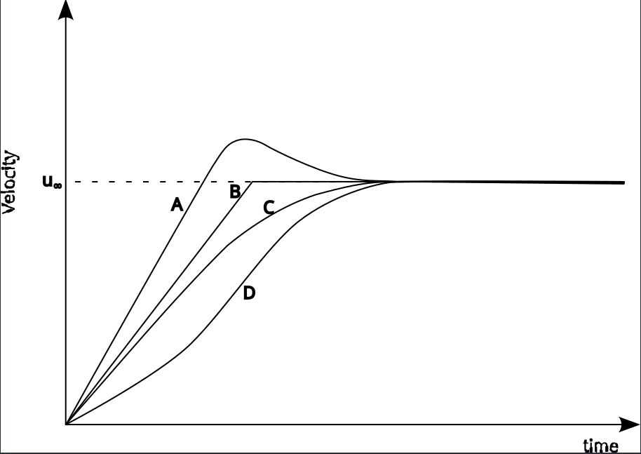
There are a number of possible ways in which the stone’s velocity can fall as a function of time. Four possibilities are shown in Fig. 3, labelled A through D. Curve A has an overshoot in velocity before reaching a steady value. This sort of thing might happen in an active control system if there is a lag between the controlling force being applied and the effect it has on the speed, but this does not seem likely in the case of air resistance, where the effect is very quick. Curve B has a discontinuity, and does not seem physically realistic. Curve C is smooth and reaches the asymptotic value gradually, so looks like something that would happen. Curve D has a saddle point, and we can’t easily find a reason for that to happen, so it looks like curve C, our exponential growth equation from Eq. \eqref{orgac57ec5}, is the correct functional form.
curves.jpg

Figure 3: Possible sketches of falling stone velocity

So we are going to assume that this is the general form for the behaviour of the falling stone. Now it may or may not be the exact form, but it has the general behaviour expected of the physical phenomenon. If the equation form is not correct, we can still deduce a time constant that we feel should be reasonably close to the exact time constant.

Trial Function

We choose as the trial function

\begin{equation}
\label{org9876284}
v^* = v_\infty (1 – e^{-t/\tau})
\end{equation}

Here the asterisk indicates that this is a trial function rather than the correct functional description for the behaviour.

Estimating the Time Constant

To get an equivalent time constant, we must substitute our test function Eq. 9 into the differential equation Eq. 5. The derivative is

\begin{equation}
\frac{d v^*}{dt} = \frac{V_\infty}{\tau}e^{-t/\tau}
\end{equation}

and

\begin{equation}
\begin{aligned}
m \frac{dv^*}{dt} &= mg – b v^{*2} \\
m \frac{v_\infty}{\tau} e^{-t/\tau} &= mg – b \left[v_\infty \left( 1 – e ^{-t/\tau}\right) \right]^2 \\
\frac{v_\infty}{\tau} e^{-t/\tau} &= g – g \left( 1 – e^{-t/\tau}\right)^2
\end{aligned}
\end{equation}

Because this is only an approximate solution, there will be a residual \(\mathcal{R}\) relative to the `proper’ solution, which is expressed in terms of the solution’s difference compared with the actual solution:

\begin{equation}
\frac{v_\infty}{\tau} e^{-t/\tau} = g – g \left( 1 – e^{-t/\tau}\right)^2 + \mathcal{R}
\end{equation}

or

\begin{equation}
\label{org68c7fed}
\mathcal{R} = \frac{v_\infty}{\tau} e^{-t/\tau} – g + g \left( 1 – e^{-t/\tau}\right)^2
\end{equation}

The value of \mathcal{R} varies with both the independent variable \(t\) and the time constant \(\tau\). This means we can only force the residual to be zero at certain values of \(t\). If we could make \( \mathcal{R} = 0\) for all values of \(t\), then we would have the correct test function, which is not generally going to be the case.

Collocation at the Half-Way Point

Generally speaking, we want to fix our solution at a point that maintains a good agreement with the actual solution over as much of the solution domain as possible. As the exponential rises from 0 to 1 at \(t = 0\) and \(t = \infty\) respectively, then it makes sense to tie our approximate solution to the actual solution (a method called collocation in the book) at \( e^{-t/\tau} = 0.5\). We do this by setting \( \mathcal{R} = 0\) at this point.

So Eq. 13 becomes

\begin{equation}
\begin{aligned}
\frac{v_\infty}{2\tau} & = g – g (1 – 0.5)^2 \\
& = \frac{3g}{4}
\end{aligned}
\end{equation}

so

\begin{equation}
\label{org7c393cf}
\begin{aligned}
\tau & = \frac{2 v_\infty}{3g} \\
& = \frac{2}{3g} \sqrt{\frac{mg}{b}} \\
& = \frac{2}{3} \sqrt{\frac{m}{gb}}
\end{aligned}
\end{equation}

and the final form of the approximate solution can be determined by substituting for \(\tau\) into Eq. 15:

\begin{equation}
v^* = v_\infty \left(1 – e^{\frac{-t}{\frac{2}{3}\sqrt{\frac{m}{gb}}}}\right)
\end{equation}

Note that in doing this we are not directly solving the differential equation expressed in Eq. 5. We are determining an approximate solution to an equivalent exponential rise problem which will have a very similar time constant. As the time constant is the useful part of the solution, this is really all we need. We are not as concerned with the mathematical correctness of the solution as we are with the physical usefulness.

Note that we didn’t have to collocate at the half-way point. We could have got a different time constant by collocating either earlier or later in the process. The best value across the domain will be the collocation at the half-way point, but if you want a better solution close to \( t = 0\) then you might want to collocate at 0.2 instead, for example. Note that one way of determining how well you have approximated the exact solution to the problem is to determine the collocation at the 0.2 and the 0.8 mark as well as the 0.5 mark. If the time constants are within a factor of 2 of one another across this range, it’s a reasonable approximation across the entire domain, for engineering purposes. Because the collocation process is fairly straightforward, determining the time constant in this way can often provide a good engineering solution with a good idea of its accuracy without ever having to solve the differential equation directly. And if you then go on to solve the exact D.E. then you will have the physical understanding of the problem to back up your solution as a bonus.

`Proper’ Solution and Comparison

In the case of a falling stone, you can directly integrate the equation and, armed with some derivative formulas or a table of standard integrals the solution is given by

\begin{equation}
v = \sqrt{\frac{mg}{b}} \tanh \left(\sqrt{\frac{bg}{m}} t\right)
\end{equation}

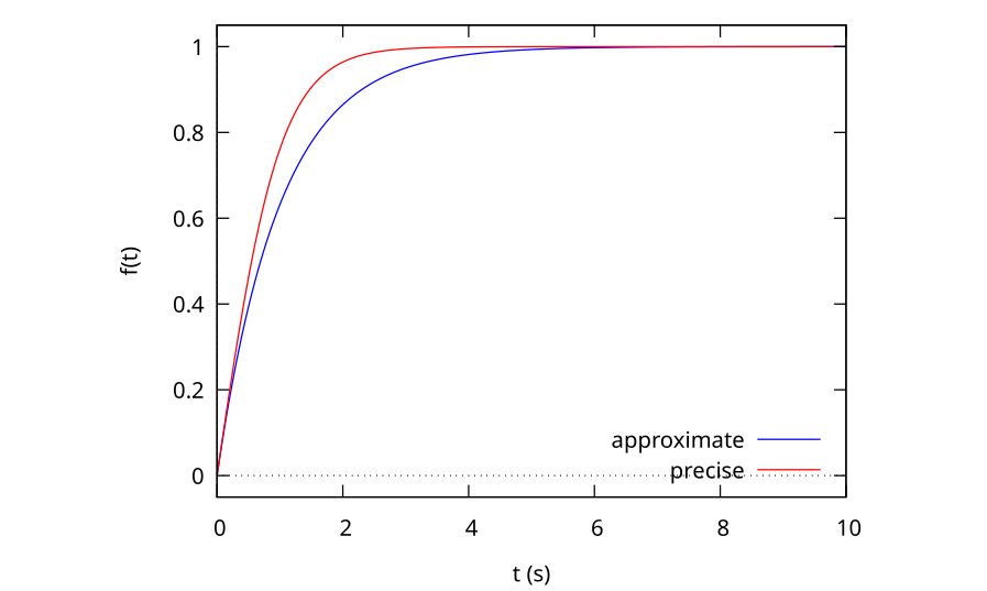
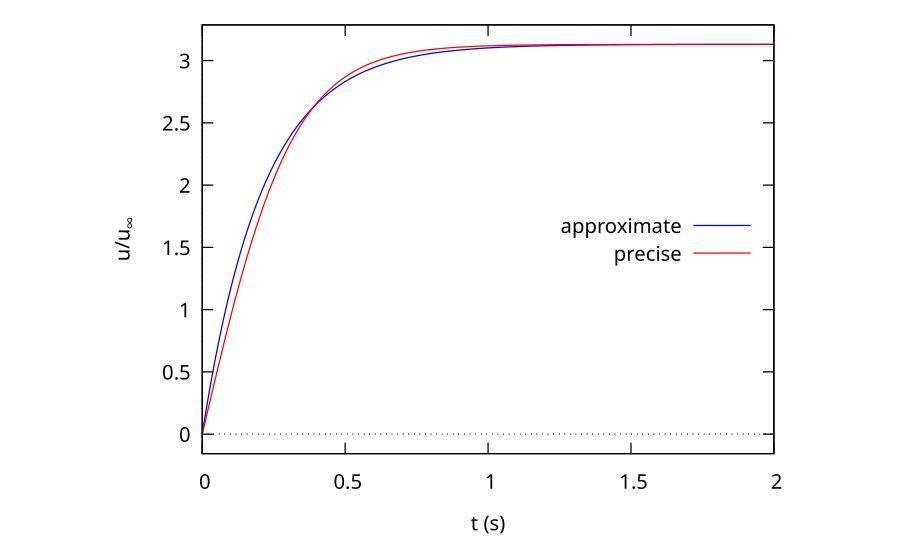
and from Fig. 4, we can see that the hyperbolic tangent form is not exactly the same as the exponential growth form, so our solution is, indeed, approximate. The general behaviour of the two functions is similar, but the exponential distribution is `fuller’ for the same time constant (\(\tau = 1\) in this case).
TanhComp.jpg

Although the physical process is not exactly an exponential growth, we can still determine an effective time constant from the mathematically correct solution, if it’s defined as the time required to grow to 63 per cent of the full velocity, in an analogous way to the exponential growth problem. When we do this we get

\begin{equation}
\tau = 0.745 \sqrt{\frac{m}{gb}}
\end{equation}

compared with the

\begin{equation}
\tau = 0.67 \sqrt{\frac{m}{gb}}
\end{equation}

obtained in Eq. 15 using our approximate form. This is around 11 per cent higher than the approximate solution, and is well within our acceptable limit of 30 per cent.

To see the difference between the two solutions, we can plot them both as a function of time, as shown in Fig. 4. It is clear that the approximate solution is very close to the precise solution, which is why the time constants are also close. The collocation point is indicated by the crossover of the approximate and precise solutions. As mentioned, we could collocate earlier to get a better fit to the earlier part of the curve or later to be more accurate later in the history.
In comparing the approximate solution to the mathematically correct one, we see that we have acquired something valuable in exchange for the small inaccuracy. Now we can express the temporal behaviour of the velocity in terms of a physical time constant that just drops out of the analysis because the exponential form is self-similar in a very similar way to how the boundary layer equation is self-similar. But this problem is a lot easier to understand.

Given that we did not solve any differential equations to achieve this approximate result, the fact that both the time constant and the general shape of the curves are so close is an indication fo the power of the technique in a predictive sense, but I think what’s even more impressive is how helpful such a process is for assisting students to understand the mathematical behaviour of the problem using some fairly straightforward physical observations.
Warp Speed in Mecrisp-Stellaris

Mecrisp-Stellaris Forth is an implementation of the Forth programming language for Arm Cortex microcontrollers. It is fast, small and elegant, and was clearly well designed. I use it in my teaching, and it’s my preferred implementation of the Forth programming language.

It can be downloaded from Sourceforge and has installation candidates for a wide range of microcontrollers. I use the STM32f103RB processor in the Olimex STM32p103 board, and sometimed the blue pill STM32f103 boards.

Out of the box, mecrisp uses the internal oscillator on the chip to run at 8 MHz. This is OK, but using the onboard PLL, you should be able to operate the chip at 72 MHz. That’s much more like it. I wanted to be able to do this, so started looking at the unofficial mecrisp guide, a site set up by Terry Porter to accumulate information about mecrisp, and about the closest thing it has to documentation. What I wanted to do was to start with the standard mecrisp forth for this processor, in a file called stm32f103rb.bin, and then add several words including this one, so I had some useful routines on the chip. Mecrisp forth makes this very easy by having two built-in words, compiletoflash and compiletoram. By running compiletoflash, any new word definitions are saved to flash rather than ram, allowing those words to be stored permanently as part of Forth. This is a really nice feature. There is also a word eraseflash that allows you to start from the original installed words, and someone has come up with a word called cornerstone that allows you to erase down to that point if you no longer need additional definitions.

If you have never seen Forth, it’s a stack-based interpreted programming environment that is conceptually quite simple. Numbers or addresses are passed on a stack as parameters to words (the equivalent of functions in other programming languages) to allow the words to perform the desired operations. Words are built from very simple building block words into more complex words by calling the primitive words in the desired order. New words can then call these words to do more complex things. Each time a new word is defined (in terms of existing words) it is compiled into a dictionary much as you would with a new word in English. As you are free to call the words whatever you like, you end up building a stack-based domain-specific programming language tailored to the problem you want to solve.

For example, you might make words that control a servo motor using pulsed-width-modulated timer. The primitive words would put the right numbers into the timing registers, and you would build your way up to having words that might address motors 1, 2, … n to turn a certain number of degrees. The program to turn the third motor by 30 degrees might look something like

3 motor 30 degrees turn

Words definitions tend to be short and closely linked to one another, because the overhead for defining a word is very small. Code tends to be fast, and takes up a small amount of memory, which is very advantageous when working with a microcontroller. You’ll see what I mean when I write the code further along.

So anyway, back to setting up the board to operate at high speed with the phase-locked loop. When I tried to use the word 72MHz as written, it would crash the board, and when that happens all the benefits of having an interactive programminh environment like Forth goes away. So I decided to move away from that code a little and start from scratch using the user manual for the STM32F103 chip. Upon looking up the appropriate registers, I was able to set the right bits in the registers that control the clocks on the chip, but it still crashed, producing a jumble of non-ascii characters on the screen and then not responding to typed text.

After many hours I worked out the problem: the original code was writing to the USART port (or serial port) 1, whereas on the STM32P103 the communications work on USART2. As the baud rate changes when the processor speed changes, the serial communication speed became all wrong, even though I thought I had fixed that (because I had fixed it for the wrong port). Once I realised this, it was a very easy fix to make the code work, and now I have 8MHz and 72MHz words that can change the speed of the processor on the fly, while keeping the baud rate at 115200 baud. Here’s the code:

8000000 variable clock-hz  \ the system clock is 8 MHz after reset

$40010000 constant AFIO
     AFIO $4 + constant AFIO_MAPR

$40013800 constant USART1
USART1 $08 + constant USART1_BRR
USART1 $0C + constant USART1_CR1
USART1 $10 + constant USART1_CR2

$40004400 constant USART2
USART2 $08 + constant USART2_BRR
USART2 $0C + constant USART2_CR1
USART2 $10 + constant USART2_CR2

$40021000 constant RCC
     RCC $00 + constant RCC_CR
     RCC $04 + constant RCC_CFGR
     RCC $10 + constant RCC_APB1RSTR
     RCC $14 + constant RCC_AHBENR
     RCC $18 + constant RCC_APB2ENR
     RCC $1C + constant RCC_APB1ENR

$40022000 constant FLASH
FLASH $0 + constant FLASH_ACR

$40010000 constant AFIO
AFIO $04 + constant AFIO_MAPR


: baud ( u -- u )  \ calculate baud rate divider, based on current clock rate
  clock-hz @ swap / ;

: 8MHz ( -- )  \ set the main clock back to 8 MHz, keep baud rate at 115200
  $0 RCC_CFGR !                   \ revert to HSI @ 8 MHz, no PLL
  $81 RCC_CR !                    \ turn off HSE and PLL, power-up value
  $18 FLASH_ACR !                 \ zero flash wait, enable half-cycle access
  8000000 clock-hz !  115200 baud USART2_BRR !  \ fix console baud rate
  $0 RCC_CFGR !                   \ remove PLL bits
  CR ." Reset to 115200 baud for 8 MHz clock speed" CR
;

: 72MHz ( -- )  \ set the main clock to 72 MHz, keep baud rate at 115200
\ Set to 8 MHz clock to start with, to make sure the PLL is off
  $0 RCC_CFGR !                   \ revert to HSI @ 8 MHz, no PLL
  $81 RCC_CR !                    \ turn off HSE and PLL, power-up value
  $18 FLASH_ACR !                 \ zero flash wait, enable half-cycle access
  8000000 clock-hz !  115200 baud USART2_BRR !  \ fix console baud rate
\  CR .USART2 
  $12 FLASH_ACR !                     \ two flash mem wait states
  16 bit RCC_CR bis!                  \ set HSEON
  begin 17 bit RCC_CR bit@ until      \ wait for HSERDY
  $0                                  \ start with 0
\  %111  24 lshift or                 \ operate the MCO from the PLL
  %111  18 lshift or                  \ PLL factor: 8 MHz * 9 = 72 MHz = HCLK
  %01   16 lshift or                  \ HSE clock is 8 MHz Xtal source for PLL
  %10   14 lshift or                  \ ADCPRE = PCLK2/6
  %100  8  lshift or                  \ PCLK1 = HCLK/2
              %10 or  RCC_CFGR !      \ PLL is the system clock
  24 bit RCC_CR bis!                  \ set PLLON
  begin 25 bit RCC_CR bit@ until      \ wait for PLLRDY

  72000000 clock-hz ! 115200 baud 2/ USART2_BRR !  \ fix console baud rate
  CR ." Reset to 115200 baud for 72 MHz clock speed" CR
;

Again, if you have never seen Forth, this might look a bit strange. The : character starts a new word definition, with the name of the word being the first word after the colon. A semicolon ; terminates the word definition. Then, if I load these definitions, I can simply type the name of the word 72MHz and the machine will start running at that speed. Backslashes indicate comments, as do the parentheses immediately after the word definition. These parentheses comments are special and are called stack constants because they remind the programmer of how many inputs need to be on the stack before the word is called, and how many remain after the word has finished running.

The constant definitions at the start of the code encode the addresses of various important registers. So after loading this file, if I were to type in AFIO_MAPR, then the address of the alternate function input-output register, $40010004 would be placed on the stack. One neat thing about Forth is how flexible it is in terms of its representation of words. For example, the word lshift is defined to take a number on the stack and shift its binary representation by a given number of bits to the left. This is like the C operator <<. So the code %011 24 lshift takes the number 3 (the % symbol represents a binary number) and shifts it left by 24 spaces, leaving the end result on the stack. So in the 72MHz word, we are able to shift the desired bit pattern into the correct locations as numbers and then logically OR the numbers together to give the number we want to put into the register to do what we want. The word that does the storing of the number into the register is ! (pronounced ‘store’). The word @ (pronounced ‘fetch’) gets the data from an address placed on the stack, so AFIO_MAPR @ would get the value currently stored in that register.

Now you may be thinking ‘lshift is a very unwieldy operator compared to <<‘. Well, one of the nice features of Forth is that if you don’t like it, you can change it easily, by defining : << ( n1 n2 --) lshift ; — again, the stuff between the parentheses in the definition is a stack comment and not code. Then you could type %011 24 << to get the same effect as lshift. The ease with which new words can be defined is either a great strength or a great weakness of the language, depending on your point of view. For some, it makes the language easily capable of conforming itself to the problem at hand. To others, it prevents the language from ever being properly standardised. Both points of view can be viewed as the correct one.

If you make a definition for a word init, mecrisp knows that it must, when stored in flash, execute the contents of that word when the controller is first booted. This allows a programmer to make a turnkey application that will run when the controller is switched on, and in this case if the word 72MHz is contained in the word init then it will be run on bootup, and the board will start running at full speed. Then, if the user wants to go back to 8 MHz operation, they can execute the 8MHz word interactively and the processor will drop back down to 8MHz.

Developing in Forth is very different to the C or arduino workflow commonly used for these microcontrollers. In the latter case, development is done on your pc, compiled to a binary program that is uploaded to the board if it compiles correctly, then executed, perhaps using a hardware debugger to ensure it’s doing what you thought it should be doing. In Forth, words are developed in RAM, tested in isolation and, when you are satisfied they work, are saved to flash from within the Forth interpreted environment. Development is done on the microcontroller via a serial terminal connection to a computer, but all the compiling is done in situ on the chip itself. In this way, you can use words like @ and ! to interrogate and change register settings in real time. Also, it’s very easy to write an assembler in Forth, allowing you to access the speed of assembly language from within Forth for those times when the overhead of the interpreter is too great (which with a processor as powerful as these is almost never, for my sorts of applications). When you get used to it, Forth can be a very powerful programming platform.

I’ve never really understood why this programming language never reached popularity in embedded programming circles. Forth has a reputation as a ‘forgotten’, or ‘old-fashioned’ language. People who say this forget how old C is. I guess C and its derivatives like arduino got a head start as a language that many programmers already knew from university courses, and I can see from an employer’s point of view it’s much easier to replace C programmers than Forth programmers — Forth code can be very idiosyncratic.

But for a small system like a microcontroller where codes are usually written by individuals or small teams, Forth’s interactivity and incremental debugging approach are very desirable characteristics. The biggest disadvantage, however, is that there is much less in the way of libraries for this language and, as in the case above, you end up doing everything at register level from scratch. Again, whether you find that an advantage or a disadvantage depends upon your viewpoint.

If you program microcontrollers and have not tried Forth, give mecrisp a try. I really enjoy programming microcontrollers this way. Who knows? You may, like me, never want to go back to the edit-compile-debug-upload-run way of doing things again!

Org-babel for J

As part of my emacs org-mode work flow, I have been using org-babel for a while. This allows you to insert code blocks into org buffers and have those blocks be executed when your file is compiled. This is a really handy method for doing reproduceable research. For example, you can call the source code function in R to do the statistical calculations for data in a table. If the data in the table changes, so will the calculation of the output data change. This prevents the perennial problem of having data in one file (typically a spreadsheet) and not knowing whether the document you generated for a paper used the 12th of September or the 15th of September version of the spreadsheet. By having explicit links to data and to the algorithm that manipulates that data, you can explicitly record the calculations you used to produce your data. And so can anyone else if they want to. This is very important for producing believeable data.

Org-babel is built into emacs org-mode, and supports an amazing array of programming languages, from compiled languages like C to interpreted languages like python or MATLAB, to specialised scripting languages like awk or gnuplot.

The best feature for me is that org-mode can read from or write to org tables, allowing a seamless integration between code and document. However, this capability differs between programming languages. Some languages, like python and common lisp, seem to be very well catered for in this regard. However my favourite programming language, J, is rather less well catered for. In particular, there does not seem to be a built-in way to pass variables to and from the code block. Instead, you can run your code as if it were a script, and the source block will provide the last calculated value as an output. For example,

#+BEGIN_SRC j :exports both
 NB. The square root of the sum of the squares of the numbers
 NB. between 1 and 10
	    [a =: %: +/ *: 1 + i.10
#+END_SRC
#+RESULTS:
: 19.6214

The output, as stated by the comment, produces the Euclidean norm of the integers between 1 and 10 inclusive, which is 19.6214, and displays it as the result from evaluating the source block. However, for other programming languages one could supply a variable argument using the :var command in the header, to pass a variable argument to a function. So, for example, the 10 in the example above could be replaced by each of the values in the column of a table.

Like most things in emacs, the code for executing commands in code blocks is available as elisp. So, in theory, it should be possible to modify the existing elisp export code to pass variables, including rows and columns in tables, to a J function. At the moment though, my understanding of elisp is not sufficiently good to be able to work out how to do this, but it sounds like a very useful thing to do, and necessary if J is to be seriously used from within org-mode. If anyone has managed to do this, I’d be very interested to know how it’s done. If not, I’ll need to learn some more elisp and try to reverse engineer how it’s already been done for MATLAB code to see if I can do something equivalent for J.

Oh, and happy new year for 2021. I wanted to get one more blog entry done before the end of 2020, as an old-year’s resolution…

Reminiscences on programming

I’ve just been thinking: programming computers has been a big part of my life ever since I was a child.  The first computer I ever got to touch was a microbee computer in year 7.  Before that I had seen some Atari 400s in Myer, and a TRS-80 at Tandy Electronics (Australia’s version of Radio Shack), but I was not allowed to play on them. Microbees were an Australian-made computer built specifically for the education market.  For some reason our school had two of these.  We were allowed to use some kind of word processor on it, but nobody at school seemed to know what to do with it.  I don’t remember much about it other than using it made me want a computer.  At around the same time as I was using the microbee at school, my father took early retirement from his job on the waterfront and we moved from Western Sydney to a very small town.  I was about 12.    My parents had never had much money, but they were keen on my education, and I was most likely constantly banging on about computers so one day to my amazement my Dad put down the unthinkable amount of $950 on a Commodore 64 with disk drive and 1 floppy disk, and a programmer’s reference guide and we walked out of the store with it.  I guess that once we had brought the (relatively inexpensive) house he had one shot at buying something for each of us:  Mum got an olive-green IBM Selectric typewriter, Dad got an air conditioner and a monstrous Kreisler TV with roll-out wooden doors and I got the Commodore.  Then we were poor again!

I would set the computer up in front of the big TV and spend hours with it and the programmer’s reference guide.  My father refused to buy games (having spent so much on the machine) so any games were going to have to be made by me.  My limit on the computer was around 4 hours sitting cross-legged on the floor until I would lose all feeling in my legs or Dad would make me do some outside work (the house was a fixer-upper).  I had no idea what I was doing, but I read everything I could.  During those times nothing else mattered to me.  I learned to program in BASIC, and read all the copies of Byte Magazine and Creative Computing trying (usually without success) to make the type-in basic programs work.  On the odd occasions I’d save up to purchase Australian Personal Computer or one of the many British Commodore magazines to find out more about programming.  But my town was no silicon valley, and there was no internet.  The only person I knew who knew how computers worked was the Hungarian TV repair man, who had to come in to fix a problem with Dad’s pride and joy (which I’m sure he thought my computer was responsible for creating…).  This fellow explained to me how flip-flops worked, which was to me like learning the mysteries of some secret society.

At my school we also had computers: Apple II/es in the maths department and a 32 kB BBC micro in the library.  Again, nobody seemed to know what to do with them, but I was happy to fill the void.  I think I was the only student who ever got to use the BBC micro.  It was hooked up to a Telstra-run bulletin board service called VIATEL, if I remember correctly, which was a very primitive text-based centrally served prototype for the internet.  You could check the weather, share prices and other things.  I didn’t get much of a chance to look at it, though, because they charged about 10 cents per page of text downloaded, and in the first day of playing with it, I managed to rack up a bill of around $65 in about an hour.  Before I had another chance to check my portfolio and play online poker I got called into the Vice Principal’s office and it was explained to me that I would no longer be using that computer…

We kept using the Apples, which were really nice machines.  Very sturdy construction, but only 8 colours on the display, compared to the amazing graphics and sound capability of the Commodore at home.  The sprite graphics were great.  I remember trying to program graphics on the Apple but getting nowhere.  I didn’t understand about things like memory mapping that would have really helped.  There was one older kid at the school (by the last name of Ward) who would make graphics of a sort by using lots of print statements strung together to make eg a car race track scroll down the page.  We looked down on these  ‘Wardy graphics’ programs as primitive, but at least he was able to make things that looked like animations, and he put so much time into it.

On the C64 you were limited to BASIC, although I knew that assembly language or a compiler was what all the professional programmers used.  But that stuff was certainly not readily available to me.  I think I will take to my grave the knowledge that POKE 53281,0 turned the background from the default blue to black, and that putting different numbers using the POKE command at location 53280 would do the same for the screen border.

Then one fateful day in 1985 I found a cartridge in the K-mart Albury bargain bin.  It was HES Forth, an implementation of the Forth programming language for the C-64.  Not only was it a much better language than Commodore basic, with a built-in line editor, but it also had a (somewhat unusual) assembler, so that now I could finally take full advantage of a computer by converting code to machine language!  I didn’t accomplish a lot, but I learnt a lot about computers and the Forth language paradigm.  In fact, I still use that language when teaching microcontroller-based instrumentation.    I remember trying to decipher the terse user manual with all its assumed knowledge, and trying to reverse engineer a prime number generating program that they included as a demo.  That really flicked a switch somewhere in my head and programming has varied somewhere between an obsession and an interest ever since.

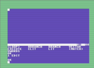
The line editor from HES Forth for the c64

All the programming since has been trying to recreate the thrill of making a computer do something I want it to do, delighting in working out some trick to use the computer to model something.  In hindsight I’m glad my Dad refused to buy me any games, though some of those Infocom titles did look pretty sweet at the time.  Instead I got hooked on a pastime I still get great pleasure from some 35 years later.

Over the next indefinite period when I can find the time, I’ll write up a little programming project I’ve started to model the Direct Simulation Monte Carlo method for simulating rarefied flows, using my current favourite programming language: J.  I’ll try to split the task into little parts and explain what I’m doing at each step, in case the 13-year-old version of me is listening.  I guess that’s what made me think of writing this post.